Monday 22 October 2012

Character Modelling Without Blueprints


Today I attempted to model a character from scracth without the use or guidance of any blueprints or images. I decided to box model my character. Below is my character so far in both the front and side view.

This was quite difficult. I was told my model was too flat half an hour into my modelling, so I tried to add more curveture to the body shape without adding any more polygons. 

Monday 15 October 2012

Character & Face modelling

Today I attempted to model a character. We were given blueprints of a character called joey.


I began by using planes and creating the outline of the eye. I then created the nose and lips and attatched the three objects. I then edited the shape of the mouth na dused the bridge and target weld tools to connect the three parts.

Above is as far as I got, so I'm gonna try and complete it later at home.

Wednesday 10 October 2012

Character Unwrap

Week 3
10/10/2012

Today I attempted to unwrap the alien character below


This character was given to us by our tutor. We were told to try and cleanly unwrap the model using the tools we learnt the last time we unwrapped. I began by applying a uv unwrap modifier. I created seams which detached the head, arms, hands, body, torso, legs and feet so they would be seperately unwrapped.


Once I did this, I pealed the model. Below is the UV map when pealed. It shows everything seperated and pealed.


The hand was much more difficult and required alot of alteration after pealing. This is how the hand looked after the alteration, not great :S.


Wednesday 3 October 2012

UV Mapping Research

Week 2
03/10/2012
Morning Session

Today we are learning about UVW Mapping. We began by doing an excersise in the morning which where we were given an item, I was given a small teddy elephant :). I was also given an a3 piece of paper and told to wrap it and then cut out the wrap.

This exercise was to help us understand how a unwrapped map looks and what it is. This actually helped me understand UVW Mapping slighty better as it showed me where the seems on an object should be.

UVW Mapping

UVW Mapping is a technique used within 3ds Max and other 3D programs such as blender which allows you to texture a whole object. This tool is an advanced tool. It allows the user to create and apply their own textures to models as seamlessly as possible.
UVW Mapping unwraps a model from a 3d image to a flat image e.g. It does this by using the mesh of the model, separating it at an appropriate seam. The most basic example of this is a box. If a box is split and flattened, but with the whole thing together, it becomes a map like the one below.


When it becomes flattened like this the whole box can be put back together easily. With this map, a user could then draw over the map and the whole model, creating a flowing texture.

This is the most basic of unwrapping techniques however; other more complicated models are unwrapped differently.

Imagine there was a real life model, for example a mannequin which you wanted to texture, you could paint the texture on to a piece of paper and then cut up and stick on the parts you want where they should be on the real model. This is the way in which mapping is explained on www.waylon-art.com, and is a good way of explaining how more advanced mesh’s are unwrapped. Below is an example of a character unwrap below.

As you can see the characters body has been broken down into pieces. The middle top part is the face, which has been split and flattened from the back of the head.


Monday 1 October 2012

Modelling task: Plane

In the afternoon we were given a plane blue print which showed the front, side and top view. Below are the blueprints:


Using tehse blueprints I had to try and model the plane the best I could, using all the techniques I know so far.

I began by creating 3 50 by 50 planes in 3D, one for each view, therefore there were two faceing sideways and one flat. in order to align them, i used the align tool and aligned the z axis to of the two upright planes to the flat one. Once I done this, I imported the blueprints into the material editor and applied them to the scene. I changed the object properties, ticking backface cull and unticking show frozen in grey. I then froze the 3 planes.

Once I had done this, I began modelling. I started by creating a box and moving it so it was aligned of the body of the side view, top view and front view. I converted the box into an editable poly and deleted the pixels from each side. I used the connect tool to create a vertical line down the middle of my object and deleted 1 side so I could use the symettry tool. I then turned the object see through using alt+x & I began selecting and looping the outside edges, extruding them along the line of the plane, using the move tool and resize tool to recreate the basic shape of the blueprint. I did this in the front view first and then the side view.

When it came to the back wing, I struggled; I was not able to remodel it well and it started giving me problems when it came to my topology on that  part of the model. Below is how my plane looke dby the end of the day:


As you can see the back looks good from the side but from the top and the front does not look right
 

3D Modelling Introduction and Basics

Week 1
Lesson 1
24/09/2012

3D Modelling
Today was the first day of the course. We began by breifly going over the basic theory of polygons. Polygons are small shapes which are manipulated and put together to make a larger shape/design within a 3d space.

After this we began to go over the basic skills of 3D modelling within 3ds Max such as:
  • Workflow
  • Viewports
  • Creating objects onto scene
  • Moving, resizing and rotating objects via X,Y and Z axis
Once we learnt these basic tools, we then went on to manipulating objects by converting objects into an editable poly. We were set the task of creating a low poly model of a car starting with a box.In order to do this we were tought the basic technique of editing shapes and polygons by manipulating verticies and edges.

This is what I created in the hour:

For the last part of the day, we learnt that a blueprint is a concept of a an object with at least two viewpoints, normally of the front and side view.

We were given a blueprint of a bird and had to try and create a model of the bird using the blueprint and skills we were taught.
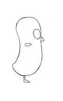


Techniques:
I started by creating two planes. I then put the two images into the material editor and applied the texture to the planes. I turned grey backface off and froze the planes.

After setting up the blue print, I created a box and turned it into an editable poly; I cut it in half & I then used the symmetry modifier so what I edited on one side would be the same on the other. Using vertex's I then moved them to the shape of the bird.

3D Modelling (Edge Loop Modelling/Topology)

Week 2, 01/10/2012
3D Modelling
Morning Session

Edge Loop Modelling/Topology
Today I learnt about how to model using edges and the transform tools. We also learnt about the way in which topology on models should be. The topology of an object should not be straight symettrical lines, but instead should be curved, unparrallel and follwing the shape and curviture of the model. The edge loop modelling is a good technique for this as it allows the creation of symetrical edges which can be easily rotated and edited without deforming the model.

To create a leg, I created a cylinder and deleted the top and bottom polygons. I then cliked on two of the top edges whilst holding shift in order to select the loop. I then held shift and used the move tool  to extrude the edge up. I did this all throughout my model until I created my leg shape. In rder to create good topology, I clicked on the edge loop I wanted to edit the geometry of and used the rotate tool.

Below are the two legs I created, with edged faces to show the topology I created.