Thursday 27 December 2012

Modelling Project: Tank Continued

05/12/2012


Today I began creating the tires for my tank. I did this by starting with a box and extruding out individual polygons equally as shown below.


I then added a bend modifier to the object and bended the object on the Z axis to the point shown below.


 I then made a copy of this tire, rotated it 180 degrees and connect the two bent edges together.

 This left me with half a tire, so I used the symettry tool and used the move tool to move the symettry mirror together with the other half. I then collapsed the symettry modifier into the object.


Collapsing the symettry left me with a fully connected tire shaped object. I then moved and scaled the tire to fit the wheel brackets and arches I left on my tank. I then made 3 copies for the other wheels.


Monday 24 December 2012

Modelling Project: Character Restart

24/12/2012

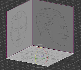
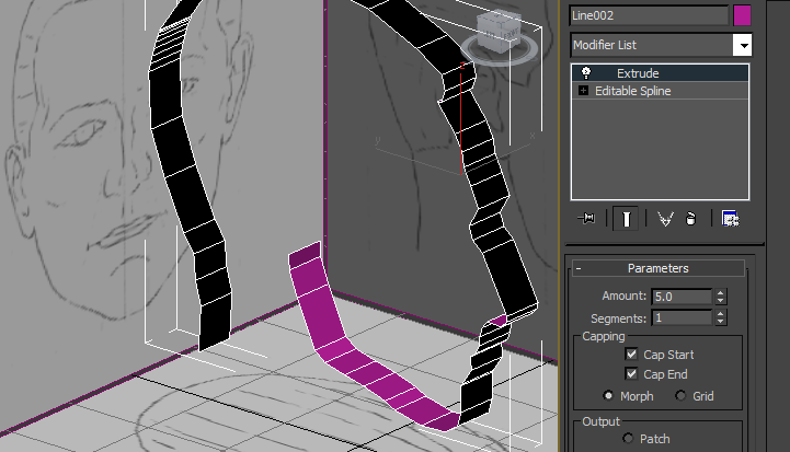
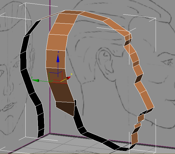
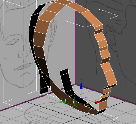
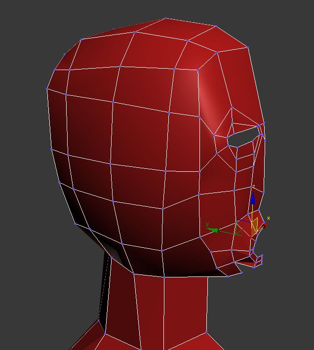
After completing my spline modelled face, I found that the topology of the shape of the face was acceptable, but the topology was not, with the face consisting of alot of pulled verts and a few triangles. This topology was hindering me in trying to add necessary detail to the face in order to make it look realistic.

As well as this, my character body was roughly modelled, very square and was not modelled with my characters face in mind, meaning the two did not fit together well when attatched.

Because of these two problems and with the advice my tutor, I began creating my character again

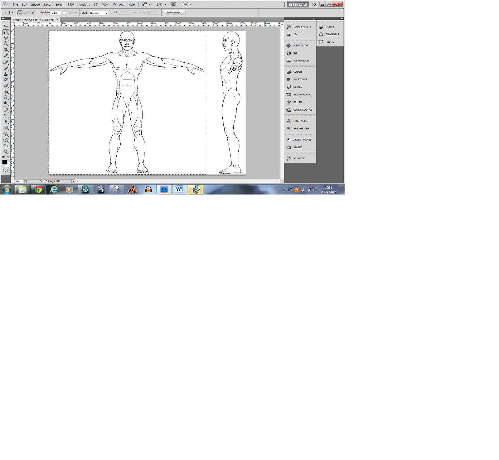
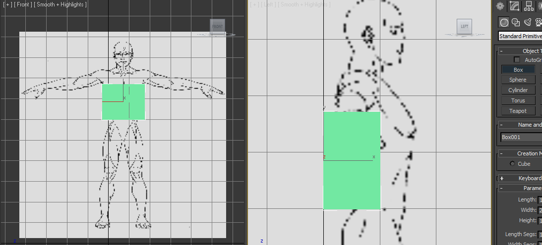
In order to get the body shape of the character correct, I downloaded a blueprint of a human male and cut it up in Adobe Photoshop. I did this by cut out each view and putting them in separate layers on a square canvas.


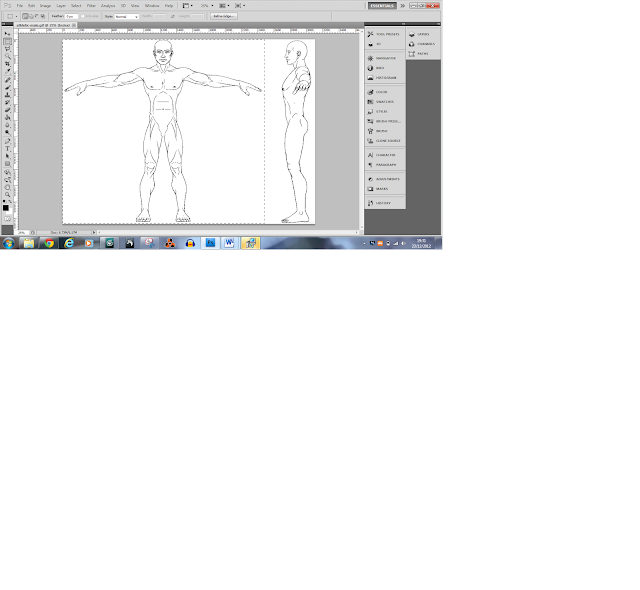
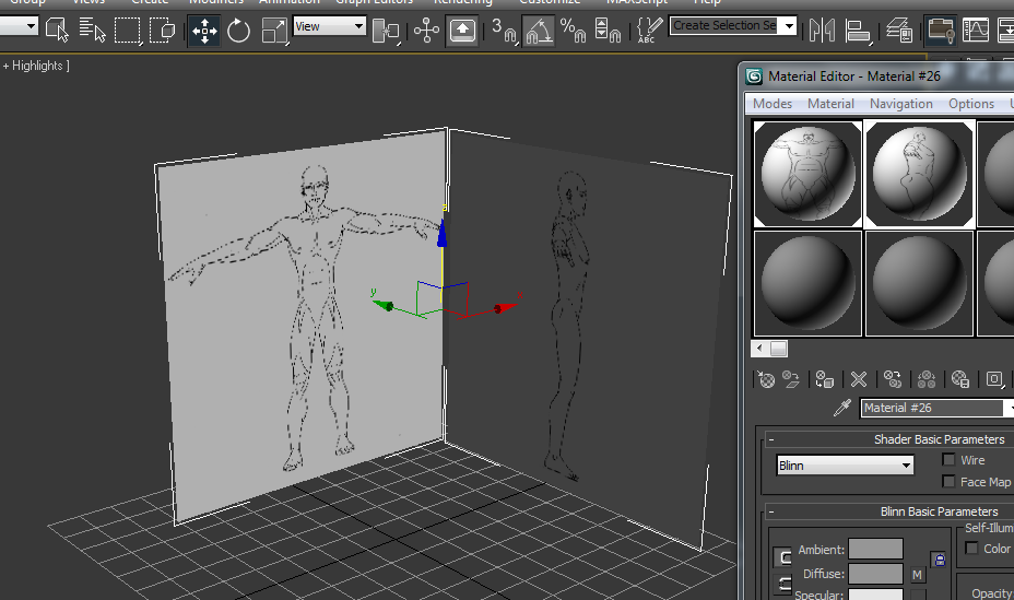
I then put these blueprints on to two 100 x 100 planes in 3ds max and froze them.


Before starting this model, I edited my viewport views to two side by side viewports one showing the front view, the other the left.

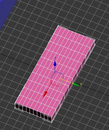
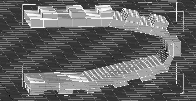
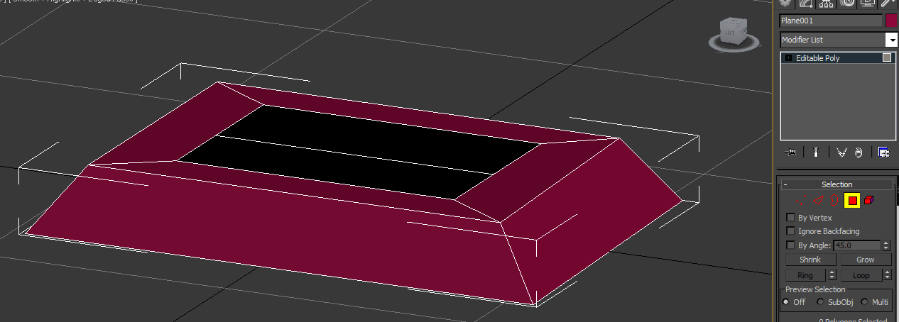
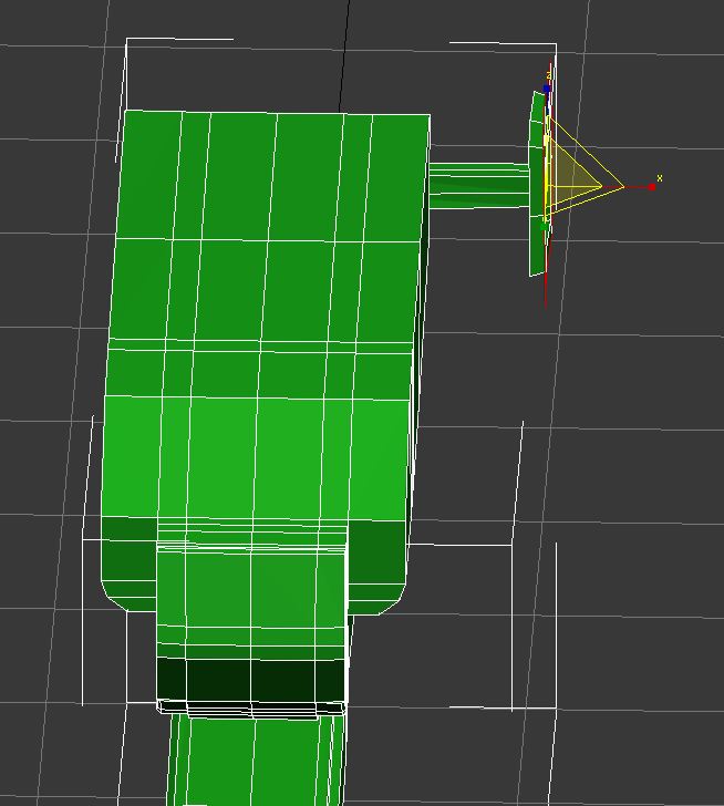
For this model I used the box modelling technique. I began by creating a box in the side view from the shoulders down to the waist. To save time editing both sides, I used the connect to create a vertical line down the middle of the box. I then deleted one half and added a symmetry modifier.


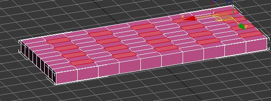
I added a another cut along the vertical of the box and used the connect settings to raise the line to around the armpit on the blueprint. I then began manipulating the verts inwards in order to create a basic shape of a torso.


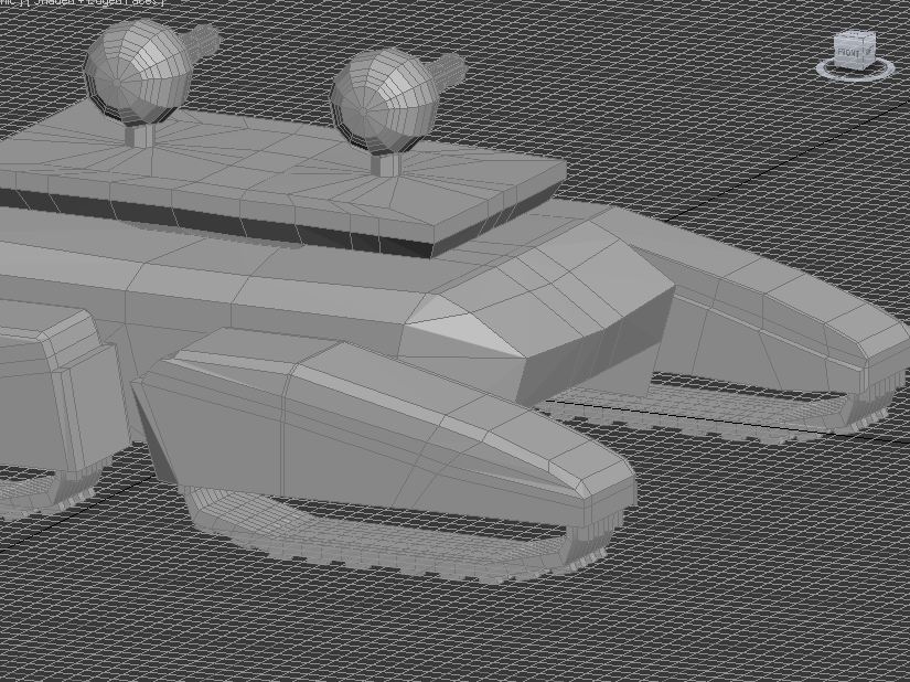
From here I used the side polygon I created and extrude it out a little and then again up to the elbow and finally upto the wrist.

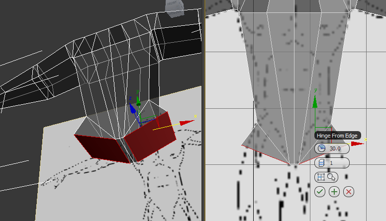
Using the connect tool I then created another vertical edge down the body. I moved the verts at the bottom close to the middle line to emulate the groin. This would give me the geometry and polygons I needed to begin the legs. Instead of using the extrude tool, I used the hinge from edge tool and chose the inside edge and used the settings to about 30 degrees creating a diagonal line and then again to create a straight polygon.


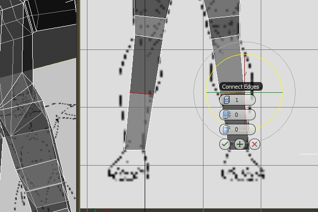
I now set up the bottom polygons to be extruded in order to create the legs. I used the extrude tool and extruded the polygon down to just above the knee, then again to the bottom of the knee and finally to the ankle. IN order to create verts for the calf, I used the conect tool to create an edge in between the around the leg in between the knee and the ankle. I used the the parameters within the connect tool to line it up with the widest part of the calf.


Wednesday 12 December 2012

Modelling Project: Face Restart

07/12/2012

I wasn't happy with my first attempt at modelling a face, so I decided to begin a new one, this time using spline modelling.

In order to get the shape of the face right, I gathered blueprints of the top, side and front of the online. The image I acquired was all together in on image, so I opened it in photoshop, cut out each side individually and resized them to match as shown in figure.


They were then placed in 3ds max and put as a material on planes.


Once the blueprints were ready, I began outlining the side shape of the head using a spline.


After creating the spline, I extruded the spline by adding an extrude modifier.


Once extruded, I converted it to an editable poly. As the face of the polygons were on the inside as shown in the figure above, I flipped the normals, leaving the front facing side on the outside of the model.


Once this was set, edge extruded from the side of the polygon on the top of the head and followed the shape of the outline of the head from the front, creating a new polygon at each curve in order to get the round shape and detail required. I extruded this down to the jawline. I then moved the edges and verts to ensure the shape was rounded and resembled a side of a head.


From here a used the bridge tool to connect the edge of the last polygon to the polygon at the chin. Using the bridge tool I added 5 more cuts in order to create the curve of the jawline after.

Within the orthographic view port  I moved each edge within the bridge I just created to match the blueprint and create a quite smooth curve. I then checked this in the perspective view port to ensure jawline looked correct from all angles. This use of view ports was a technique I used regularly within this creation process in order to ensure the overall shape of the face was correct.


Tuesday 4 December 2012

Modelling Project: Robot Start

For my project I am creating a number of future military weaponry. One of these weapons is a large robot like machine which is mainly used as a riot disperse tool.

For this robot, I began using research and visions of other peoples robot creations as well as real military robots in development.

 When creating this model I decided to use plane modelling beginning at the foot.


I then edge extruded up from this plane and created the shape of a leg.

Although the robot I am creating will be quite squared, detail was still required to give the model its shape and design. This was done a number of different ways, but mainly with the use of the connect tool.

With the leg completed, I had the option to create the body separately and attach it to the legs or continue creating the body from the same plane, I chose the latter.

Monday 3 December 2012

Modelling Project: Character Model

03/12/2012

I attempted to carry on with my character model and add detail to the face in order to make it look close to reality; however when attempting this, I realised that the topology of the face was not good and caused problems to me creating and adding key details to the face, especialy the eyes, nose and jaw. I attempted to to delete some poly's, but ended up creating triangles, so I decided that it would be far more beneficial to start the face model again, using a blueprint.