I wasn't happy with my first attempt at modelling a face, so I decided to begin a new one, this time using spline modelling.
In order to get the shape of the face right, I gathered blueprints of the top, side and front of the online. The image I acquired was all together in on image, so I opened it in photoshop, cut out each side individually and resized them to match as shown in figure.
They were then placed in 3ds max and put as a material on planes.

Once the blueprints were ready, I began outlining the side shape of the head using a spline.
After creating the spline, I extruded the spline by adding an extrude modifier.
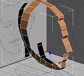
Once extruded, I converted it to an editable poly. As the face of the polygons were on the inside as shown in the figure above, I flipped the normals, leaving the front facing side on the outside of the model.

Once this was set, edge extruded from the side of the polygon on the top of the head and followed the shape of the outline of the head from the front, creating a new polygon at each curve in order to get the round shape and detail required. I extruded this down to the jawline. I then moved the edges and verts to ensure the shape was rounded and resembled a side of a head.
From here a used the bridge tool to connect the edge of the last polygon to the polygon at the chin. Using the bridge tool I added 5 more cuts in order to create the curve of the jawline after.
Within the orthographic view port I moved each edge within the bridge I just created to match the blueprint and create a quite smooth curve. I then checked this in the perspective view port to ensure jawline looked correct from all angles. This use of view ports was a technique I used regularly within this creation process in order to ensure the overall shape of the face was correct.


No comments:
Post a Comment